AriCalculator is a home made pocket calculator.
Hardware
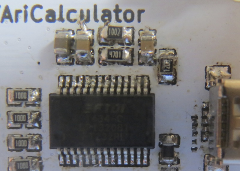
The hardware is based on NXP's MC9S12G micro controller family. It has a 38 button key pad and a ST7565R based 128×64 dot matrix LCD display (optionally back lit). As of RevC, the AriCalculator also has a general purpose 3.3V SPI expansion port.
Software
The software for the AriCalculator will be written in Forth. This will make it easier to port it to other platform and to add new features.
Latest Updates:
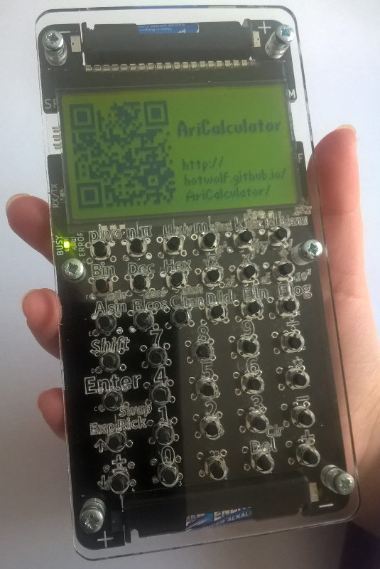
14 May 2017 - First usable firmware
Daniel managed to get his four-function firmware running on the handheld hardware. The AriCalculator has it’s first real firmware:
After all these years of proof-of-concept firmwares, it is very nice to have a working calculator.
Thank you Daniel for your great work!
01 May 2017 - Four-function calculator
Daniel already has the basic floating point operations working on his S12G based prototype.
Very impressive!
11 Mar 2017 - Welcome Daniel
Daniel Milutinovic has joined the AriCalculator project. Daniel has already created a working 8051-based homebrew calculator. With his help, the AriCalculator will receive a real firmare to become a functional handheld calculator.
Daniel already has some remarkable results to show for on the S12G microcontroller platform:
Thanks Daniel, for devotiong your time to this project!
05 Mar 2017 - Black AriCalculator
In August last year I published the AriCalculator as “recipe” on the Seed Studio comunity pages. In return I received a discount on PCBs, which I spend on a set of back AriCalculator boards. This is how they look assembled.
The black solder mask prvides a better contrast to the laser engraved lables.
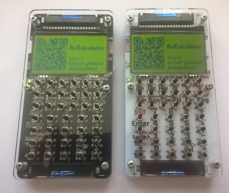
Overall black is a pretty niche color for the AriCalculator.
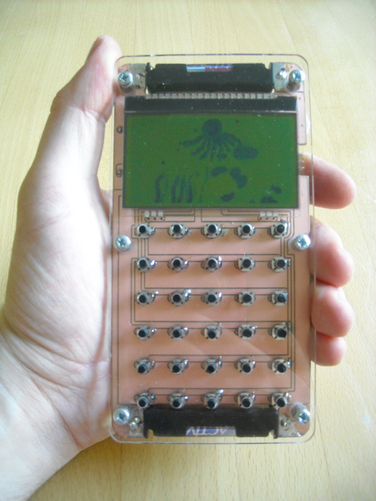
10 Jan 2015 - First RevC Calculator Assembled
The first RevC calculator nas been built. I still need to do something to improve the contrast of the keypad labels.
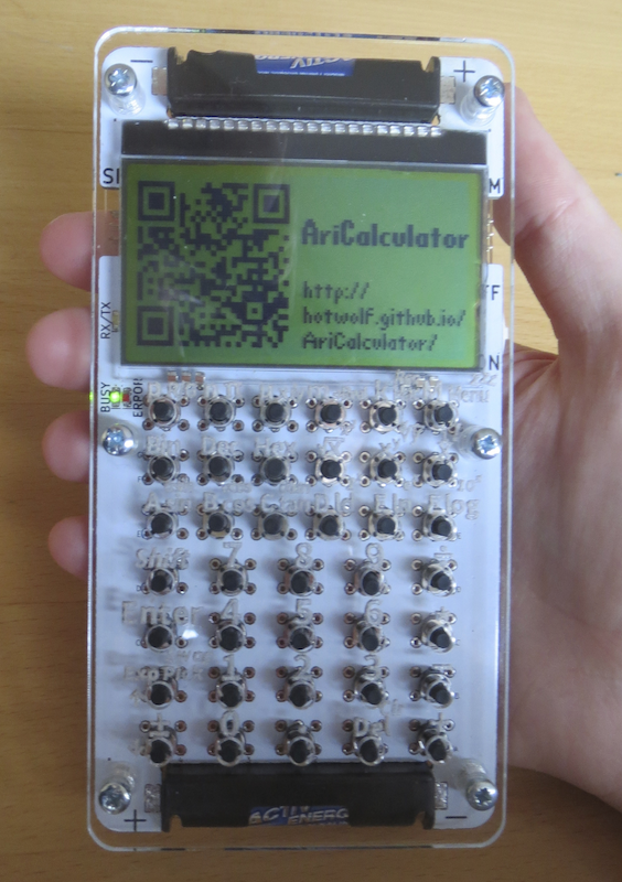
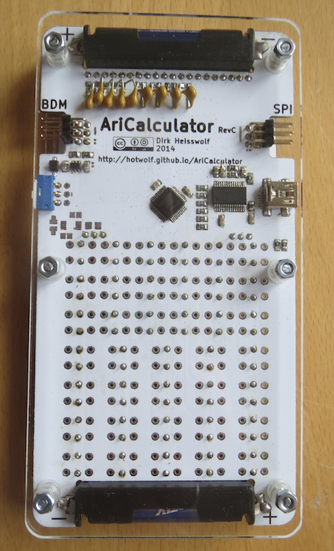
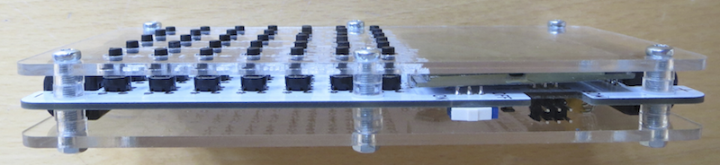
RevC comes with lasercut acrylic spacers.
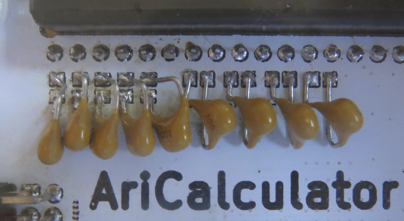
I was out of 1uF SMD capacitors, but the PCB has enough room for through hole components.
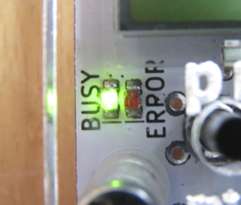
During the PCB assembly I’ve discoverd one design bug: LED1 and LED2 have been flipped the wrong way around in the
schemactics. Therefore the cathode markings
on the silkscreen are on the wrong side. The design files have been corrected in the current git commit.
There had also been a mistake in the assembly plan:
resistor labels R9 and R10 had been swapped (also fixed in the current commit).
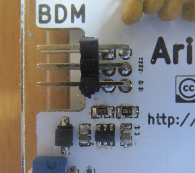
A further pitfall is the orientation of resistors R11 and R12. The assembly plan
didn’t give any hint that they need to be mounted horizontally, whereas all neighboring components ate aligned vertically.
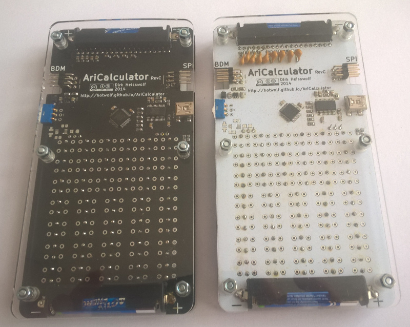
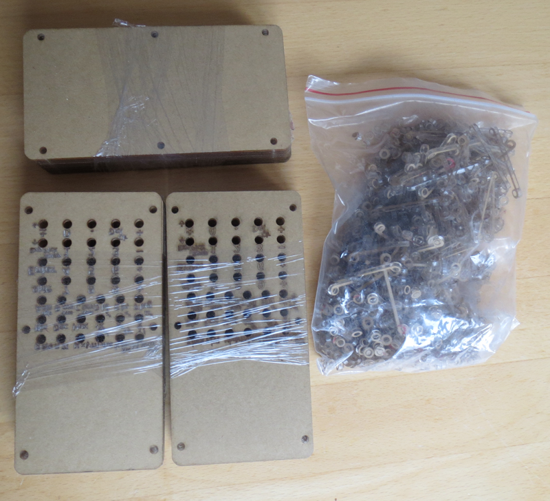
03 Jan 2015 - RevC Boards and Enclosures Have Arrived
My order of RevC boards and enclosures has come in the mail.
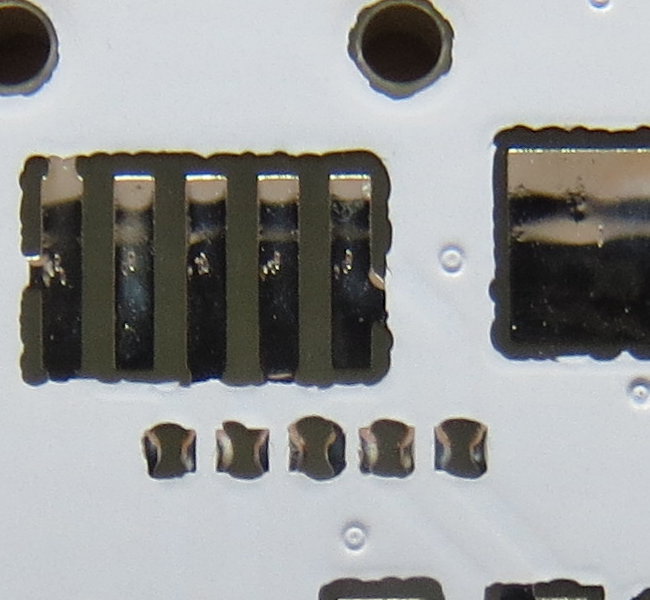
This is the first time that I’ve added tiny spark gaps to all exposed board inputs. They turned out well (no shorts).
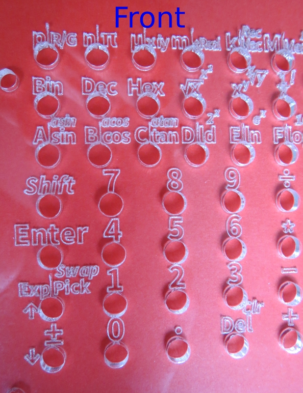
For the enclosure of RevC, I’ve tried out Seeedstudio’s new laser engraving service.
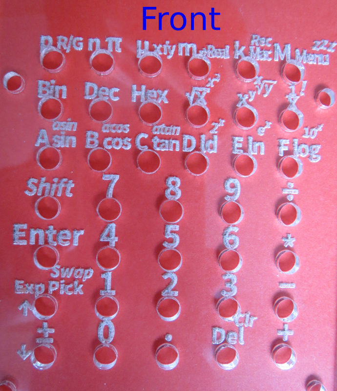
I’m sure it wasn’t easy to burn the small print of the calculator’s keyboard lables into the clear acrylic cover.
The people at Seeedstudio were really nice and experimented with my design to improve
readability. In the end they sent me two versions of the engraved front covers. One has a filled font (this is basically
what my original design looked like):
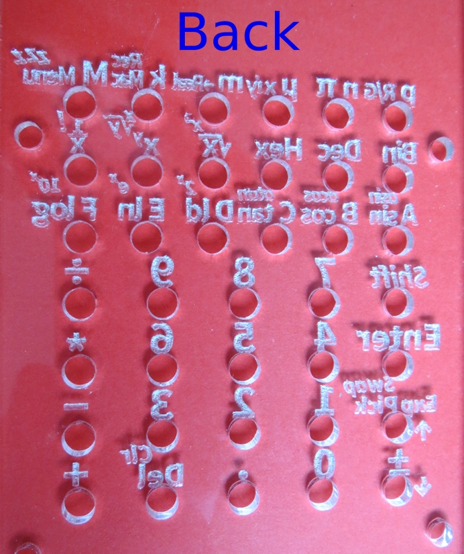
The other variation uses an outlined font.
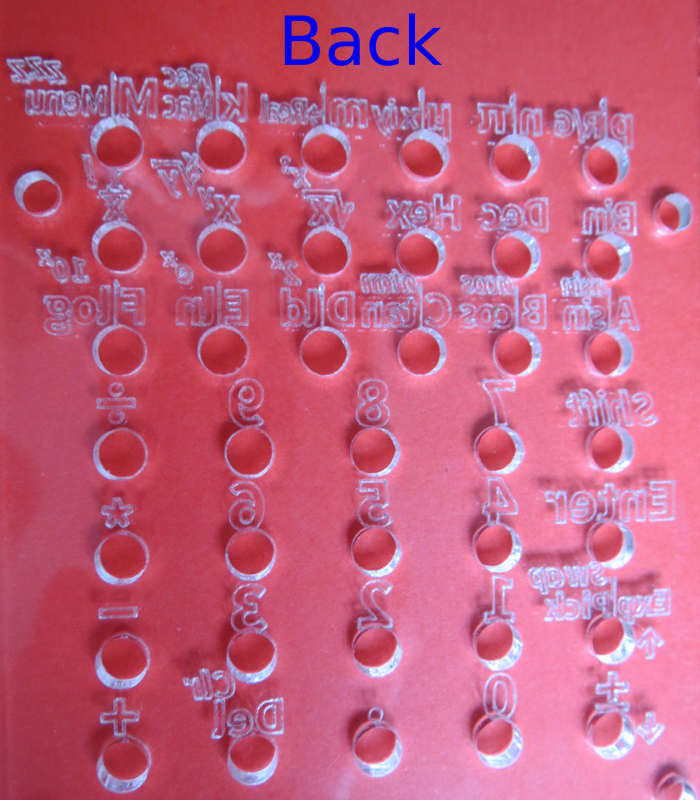
I think they both turned out well.
Now I need to come up with a good way to color the engraved labeling. Maybe I should have ordered black PCBs instead of white ones.
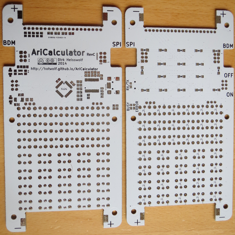
16 Dec 2014 - Redesign Complete
The prototype of the AriCalculator (RevA) is no longer usable. It has been destroyed in an attempt to replace a broken FTDI USB to serial converter. After a first attempt to fix the prototype’s design flaws with incremental changes (RevB), I’ve decided to do a full redesign (RevC):
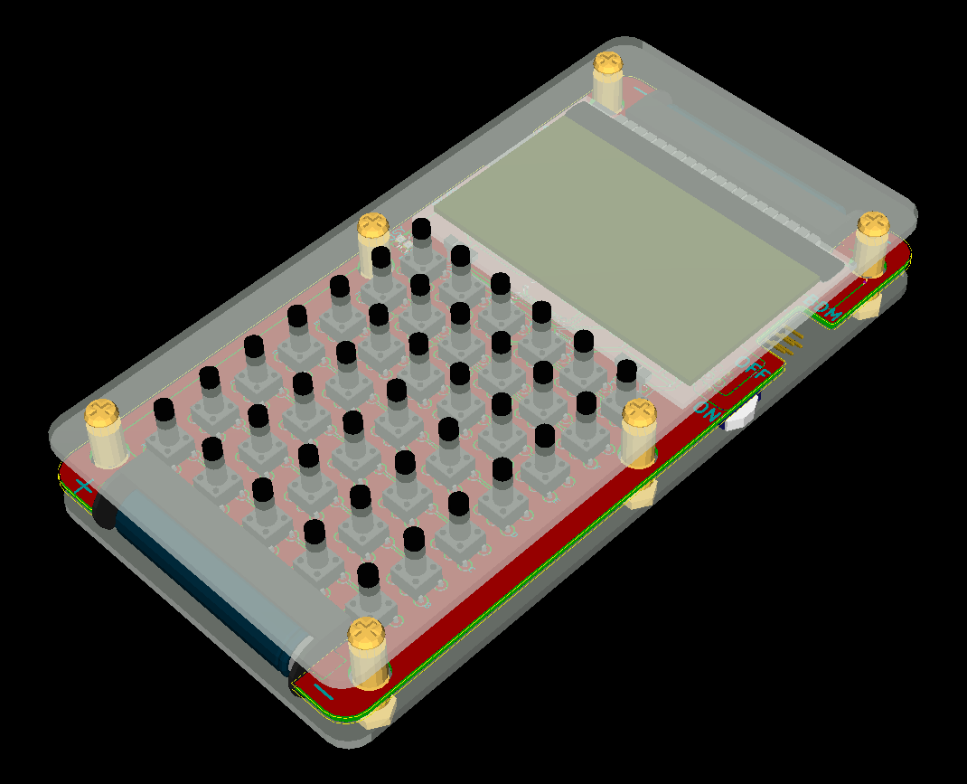
The new design no longer uses a milled PCB in combination with an S12-Micro-EVB. Instead it uses a single PCB, which makes assembly and repairs much easier. The new design has new features like an extended keypad (38 instead of 30 keys), an expansion port (SPI), and a back ight option for the display. However, it is not fully compatible to the previous designs.
PCBs and enclosures have already been ordered and should arrive in January 2015.
07 Jun 2012 - Added Schematic on Upverter.com
I drew a schematic for the AriCalculator’s main board on upverter.com.
06 Jun 2012 - Project Listed on Upverter.com
The AriCalculator project is now listed on upverter.com .
25 May 2012 - First Prototype Built
The first calculator hardware (RevA) has been built and it works! My daughters actually soldered most of the main board. I found a couple of bugs and design flaws, but nothing that couldn’t be fixed. Here are some pictures:
The buttons I’ve used are not meant for top side soldering. This made the the assembly unecessary difficult. RevB will contain vias and the leads of the buttons will only be soldered from the bottom.
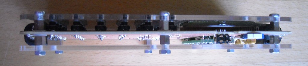
The calculator is about 18mm thick. Right now I’m using a reflective LCD (EA DOGL128L-6), which fits right in the available space. If I will aver add a backlight, I will need to move the MCU board underneath the keyboard.
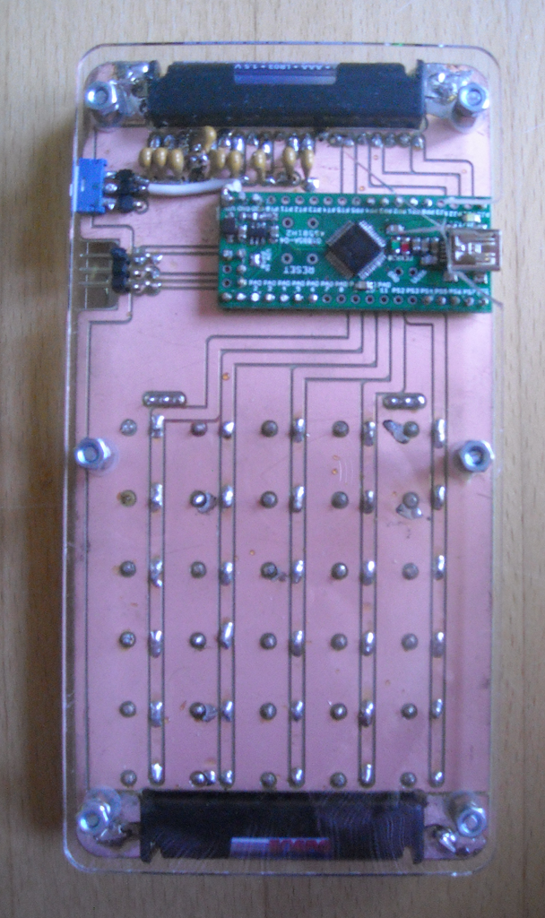
The back side shows most of RevA’s problems. The MCU’s supply is not connected, one of the LCD’s capacitors is connected to VBat instead of GND, the pads of the on/off switch are not close enough to the edge of the board, and the back cover doesn’t have a cut out for the USB connector. I broke my back cover trying to cut it out manually.
All bug fixes and design improvements have already been applied to the RevB design. However I don’t plan on building RevB for a while. For now I’ve got a working hardware that I can use for software development.